Medical grade BLDC motor FOC Controller with LCD and fiber optic wire control
- Rotem Segev
- Nov 9, 2025
- 3 min read
We designed a high-precision embedded control platform designed to drive a BLDC motor using Field-Oriented Control (FOC), control the position of a fiber-optic light delivery wire for medical therapy, and provide a user-programmable motion interface via a full TFT touch display.
The architecture uses two dedicated STM32 MCUs for deterministic motor control and robust system management.

System Architecture
Main Control Unit – STM32H743
Runs the UI, system logic, scripting engine, safety supervision, logging, and communications
Drives the 2.4" TFT LCD capacitive touch screen (240×320)
Loads files, animation assets and logs from SD card and external SPI Flash
Monitors power domains (battery/charger/Vin) and system health
Issues motion commands to the motor MCU over UART
User defines motor movement scripts via touch UI
Manages:
RGB status LED
Touch input, buttons, external sensors
Error logging to SD
USB/UART communication with host device
Motor Control Unit – STM32H750
Dedicated FOC motor controller
Implements closed loops for:
Position
Speed
Current (torque)
Interfaces with:
Magnetic encoder (12-bit, absolute)
Hall sensors (internal + external)
Friction wheel IR encoders
Light interrupters for safety zones
Shunt current sensors (INA240)
Executes motion trajectories received from main MCU
Reports status, errors, and feedback in real-time

Unique Mechanism – Fiber Optic Wire Positioning
A medical fiber optic wire is mechanically moved by the BLDC motor. To determine its precise position:
Sensor | Purpose |
IR1 / IR2 / IR3 | Detect wire motion and motion validity (Go/No-Go safety) |
Friction wheel IR encoder | Tracks actual wire displacement and direction |
Absolute Hall sensor | Reference Point B – guarantees repeatable absolute stop |
Motor internal encoder | Reference Point A – relative position |
STM32 FOC loops | Maintain accurate motion, torque, and velocity |
This allows the system to always locate and return the wire to the exact same position, even after power cycles.
The wire emits strobed light for medical therapy, synchronized to the movement script.
Motor & FOC Capabilities
The system incorporates advanced motor control features:
Field-Oriented Control (FOC) for maximum torque efficiency
4-quadrant operation
Low-speed torque stability
Velocity and position loops with PID
5.5V – 24V motor supply
3A continuous / 5A peak output
Integrated 12-bit magnetic encoder
Script-driven motion profiles
C++ / Python controllable through library
Motor driver: L6234 3-phase bridge
Current sense: INA240 high-precision bidirectional amplifier

Power System
Multi-stage protected power design supporting:
Mode | Behavior |
Vin primary | Charges battery, powers system, disables battery load |
Battery mode | Runs system from 18650 pack |
Sleep mode | Partial shutdown, wake from touch/button |
Components include:
Hot-swap and protection: TPS25983 (2.7–26V, 18A, transient protected)
Battery charger: BQ25308 (1-cell 3A charging)
Buck 5V, Boost 12V, Multiple LDO rails
Over-current, over/under voltage, load monitoring
Clean ground segmentation and EMI filtering
Physical Interfaces
Interface | Function |
TFT LCD + Capacitive Touch | UI for setting motion scripts |
SD Card | Logs, images, configs, motion programs |
External SPI Flash | Failsafe boot storage |
UART to host | Diagnostics, control |
Multiple sensor JST/Pico connectors | Wire location, safety, encoders |
Trigger button | Start motion |
Motor connector | BLDC + Hall + encoder |
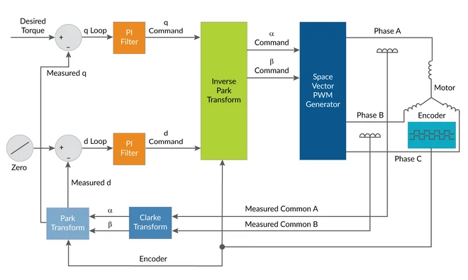
FOC Control block diagram
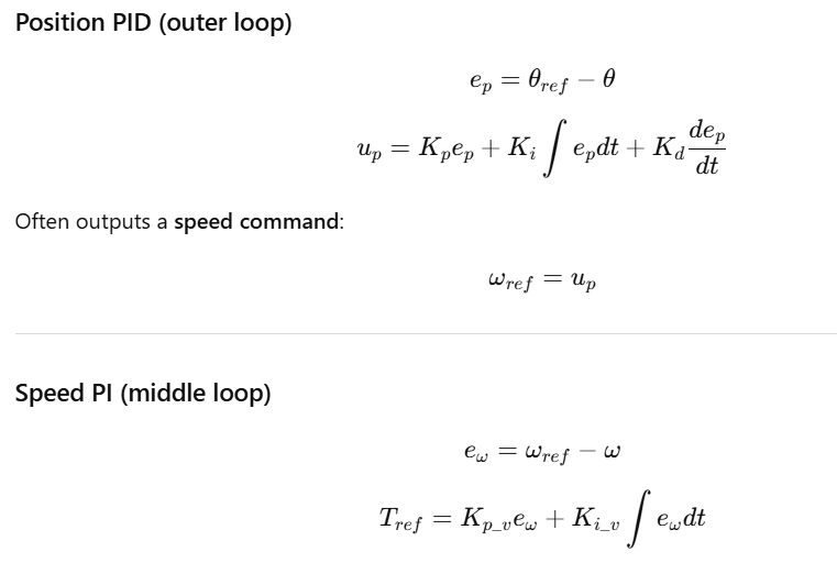
And this is the complete PID loop:

photos of the assembled system:


How did we compute the FOC algorithm parameters:
Outputs a torque or current reference.
Clark Transform:

Park Transform:

Current PI gains:

Inverse Park:

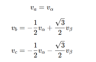
Inverse Clark to drive voltages (SVPWM):
Stage | Equation Purpose |
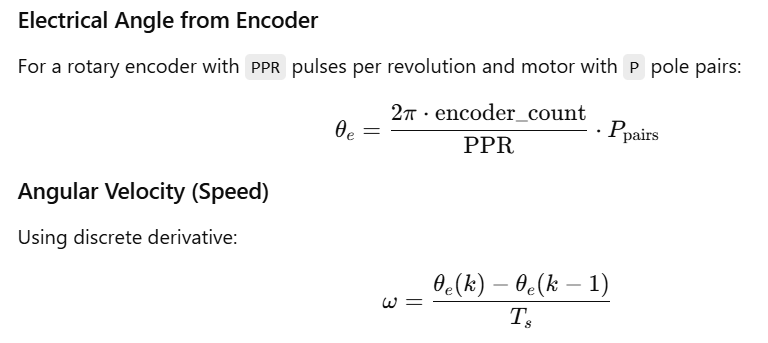
Encoder | Compute θe,ω |
Position PID | Convert position error → speed ref |
Speed PI | Convert speed error → torque/current ref |
Clarke | Convert 3-phase currents → iα,iβ |
Park | Convert to id,iq using θe |
PI Current loops | Generate vd,vq to correct error |
Inverse Park | Convert back to vα,vβ |
SVPWM / Inverse Clarke | Generate 3-phase PWM signals |


Comments